
Navigate to the settings.
- Get “BLERTK” app from the App Store for iOS or Google Play for Android.
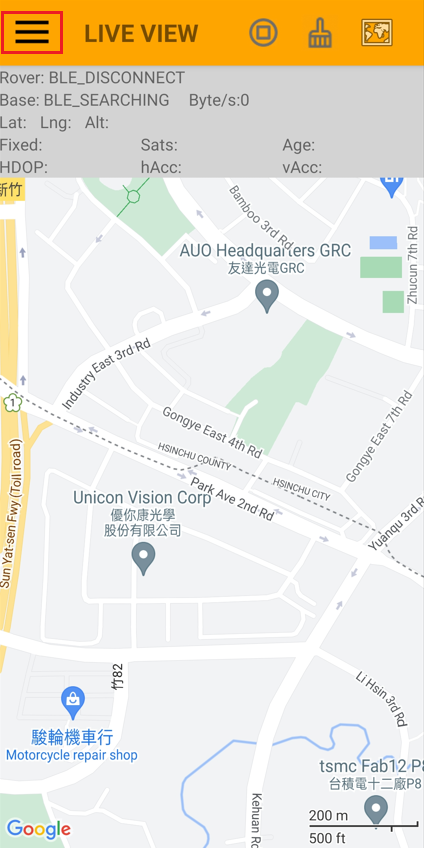
2. Open BLERTK and tap the menu icon to access additional features.
3. Click ”Rover”
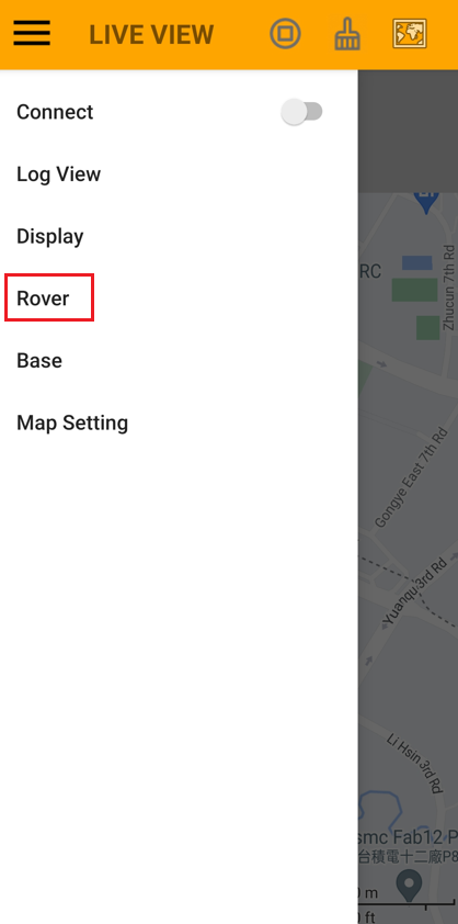
4. Click “Rover Source” and select “Bluetooth LE”.

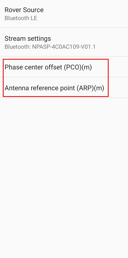
5. Click “Stream settings”
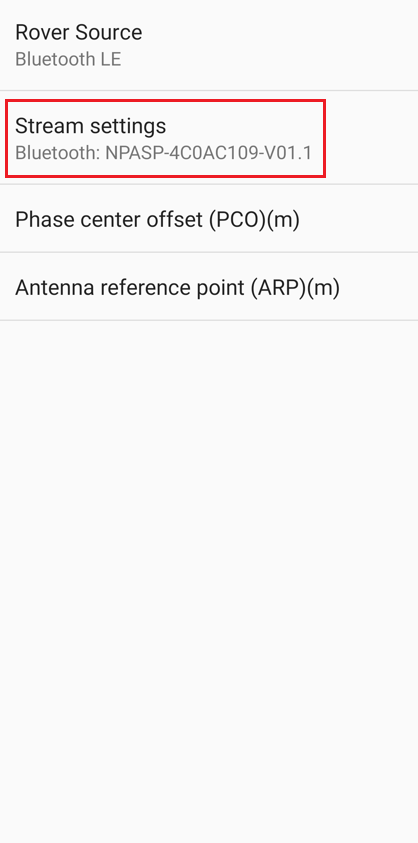
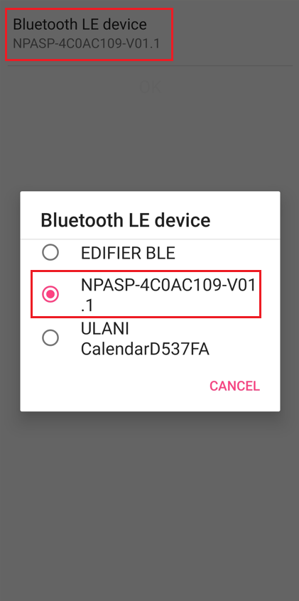
6. Click “Bluetooth LE device” to choose a GR-9029 starting with “NPASP-xxx”.
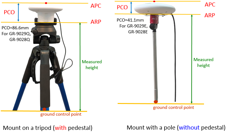
Explain Phase Center Offset (PCO) and Antenna Reference Point (ARP):
7. Enter the Phase Center Offset (PCO) and Antenna Reference Point (ARP) for rover GR-9029.
Terms:
Ground Control Point: A known point with predetermined (latitude, longitude, height) coordinates.
APC (Antenna Phase Center): The average point from which the antenna phase is measured.
ARP (Antenna Reference Point): The access point on the antenna’s lowest horizontal surface.
PCO (Phase Center Offset): The offset between the average APC and ARP.
ARP Height: The height measured from the ground control point to ARP.
Please note:
- The antenna is positioned above the ground control point.
- Height adjustment ensures accurate positioning of either the antenna or the ground control point.
- For the rover (GR-9029), the adjustment involves subtracting the height (PCO + ARP) from the antenna height, allowing it to be saved as a known ground control point.
- If the PCO and ARP values are entered, the new position will be applied accordingly. Specifically, for the rover, the displayed height will be that of the ground control point, i.e., PCO + ARP is subtracted from the antenna height.
8. Go back to the main menu and tap the hamburger icon to choose “Map Setting.”
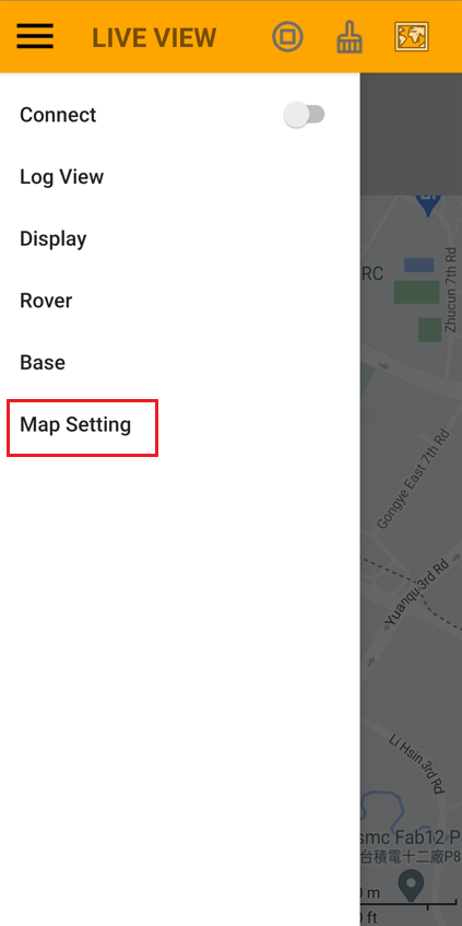
9. Enable “Draw Distance”

Explain “Geodesic distance” and “Ground distance”:
9. Click “Distance Type” and select “Geodesic distance” or “Ground distance”.

Terms:
Geodesic distance measures the distance between two points at sea level, disregarding altitude.
Ground distance, factors in altitude, providing a true distance in the terrain where surveyors.

10. Go back to the main menu and tap the hamburger icon to choose “Connect.”

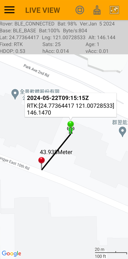
11. When the central green human icon turns green, it means RTK is fixed.

12. Press the button on the cable of GR-9029 to create a pin, i.e., to log a position or POI (Point Of Interest). A popup window will appear for the pin. Click the window to edit pin notes.

13. Press the button on the cable of GR-9029 again to create another pin. Note that different “Distance Type” settings in “Map Setting” display varying distance values.
Navisys RTK GNSS can be purchased from:
https://gpswebshop.com (US & WorldWide)
https://canadagps.ca (Canada)