
(If you purchase a TOP168 RTK GNSS receiver from GPSWebShop, there's no need to follow this article. The device comes with factory default settings that already cover these configurations. You can safely skip this article.)
Real-Time Kinematics (RTK) technology enables acquiring positions with extremely high accuracy. However, RTK relies on receiving RTCM correction data from a base station. If you don’t have access to an RTK base station in your area, setting up your own can be a practical alternative. This guide will provide step-by-step instructions on how to set up a TOP168 GNSS Receiver as an RTK base station. If you’re using a different model of (ZED-F9P) RTK GNSS receiver, there could be some minor differences, but the general process should be similar.
1. Download and install the configuration tool
If you already have the “u-center” software installed, please proceed directly to section 2. If not, you will need to download it from the u-blox website at
https://www.u-blox.com/en/product/u-center
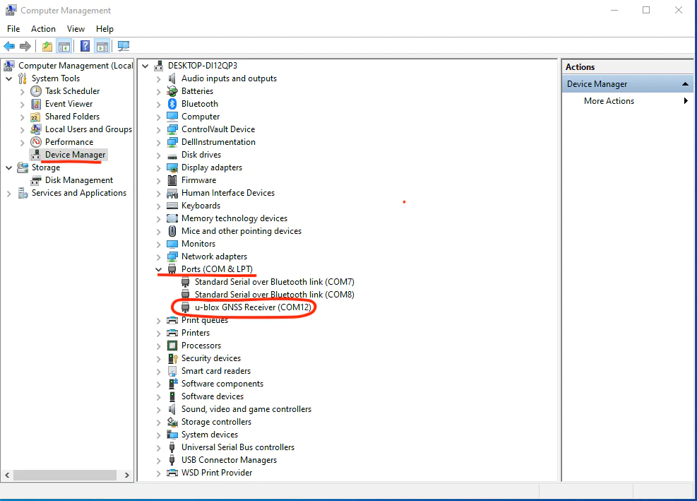
For the TOP168 or any other ZED-F9P GNSS receiver, please select the edition that is compatible with “F9 / M9”. Once downloaded, install the u-center software on your Windows computer, and then connect the TOP168 GNSS receiver to a USB port. Open the “Device Manager” and navigate to “Ports (COM & LPT)” → “u-blox GNSS Receiver (COMxx)” or “USB Serial Device (COMxx)”. In the example below, the COMxx port is COM12. Take note of this COM port number, as u-center needs to connect to this specific port in order to communicate with the TOP168.
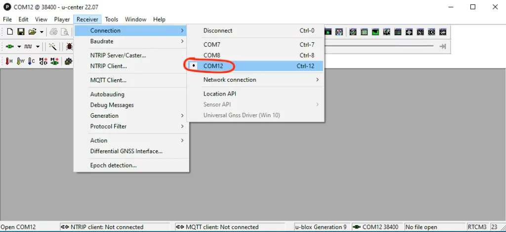
Open the u-center software. From the menu, go to “Receiver” → “Connection” and choose the COM port you previously noted down from the Device Manager, which in this case is COM12.
2. Turn on RTCM3 message types
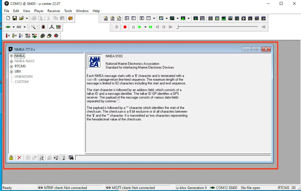
In the u-center menu, go to “View” → “Message View”. This will open the message view window.
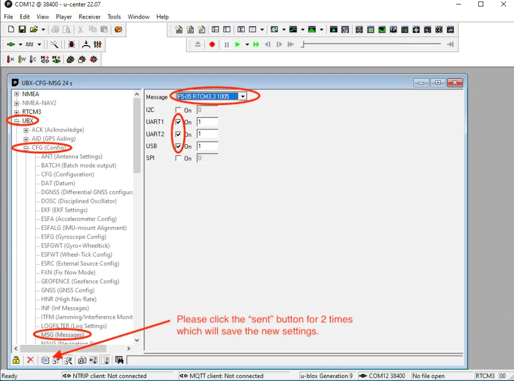
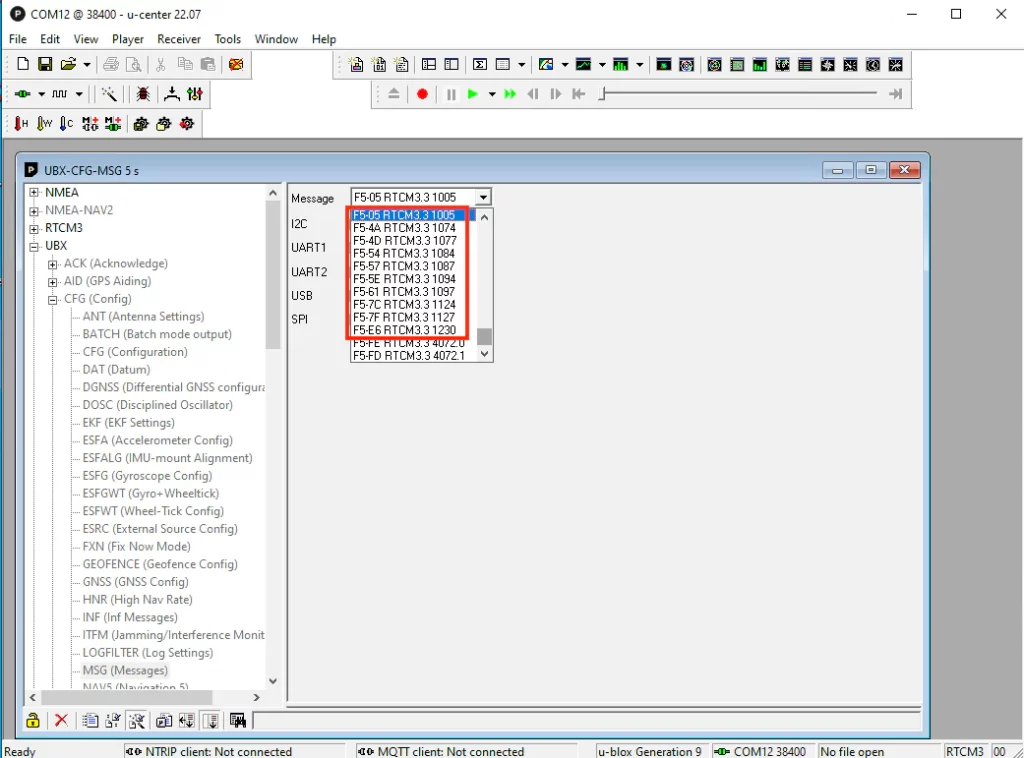
In the “Message View” window, click on “UBX→CFG→MSG”. On the right panel, select the message “F5-05 RTCM3.3 1005”. Enable UATR1, UATR2, and USB. To save the settings, click the “Send” button twice. (Note: In u-center, you need to press the “Send” button twice every time you want to save the settings on the current screen.)
Other than the “F5-05 RTCM3.3 1005”, do the same for Message types below.
“F5-4A RTCM3.3 1074”
“F5-4D RTCM3.3 1077”
“F5-54 RTCM3.3 1084”
“F5-57 RTCM3.3 1087”
“F5-5E RTCM3.3 1094”
“F5-61 RTCM3.3 1097”
“F5-7C RTCM3.3 1124”
“F5-7F RTCM3.3 1127”
“F5-E6 RTCM3.3 1230”
Enable the UATR1, UATR2, and USB options, and press the “Send” button twice for each message type.
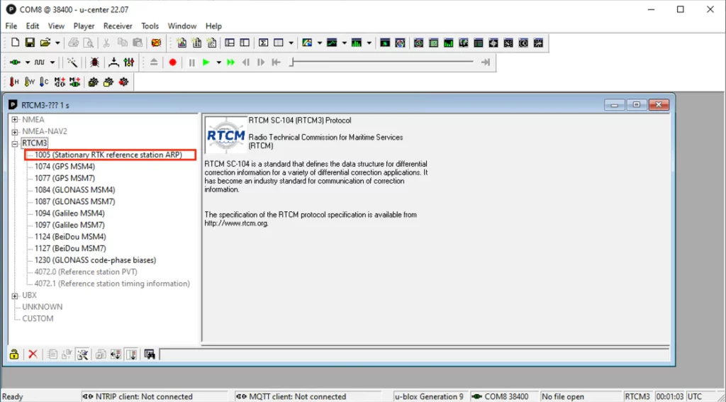
Next, in the left panel of the “Message View,” if you select “RTCM3,” you will notice that the RTCM message types 1074, 1077, 1084, 1087, 1094, 1097, 1124, 1127, and 1230 transition from being “Grayed out” to “Black.”
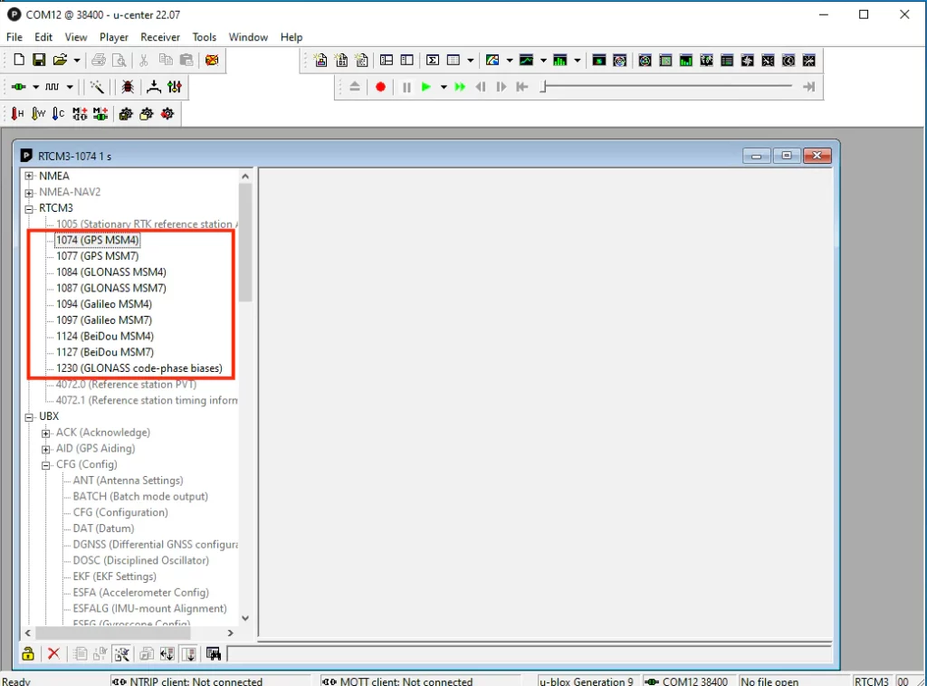
The message type 1005 may still appear as “Grayed out” at the moment, which is normal. It will transition to a “Black” font as soon as the Base Station finishes initializing.
3. Acquiring the Base Station Location
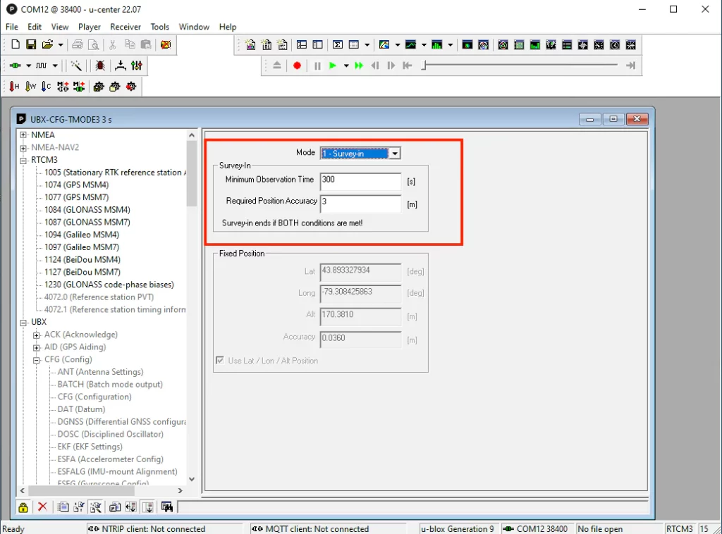
In the Message View window, navigate to UBX→CFG→TMODE3. The Time mode (TMODE3) setting determines how the receiver acquires the base station’s location. You have the following options to choose from: 1, 2, or 3.
0 – Disabled (Disable the RTK base station mode)
1 – Survey-in
2 – Fixed Mode
“Survey-in” (Option 1)
If you are deploying the GNSS base station at a temporary location, you can utilize the “Survey-in” method to acquire the base station’s position. This process can be completed in just a few minutes. Survey-in involves estimating the receiver’s position by calculating a weighted mean of all valid 3D position solutions. When configuring the survey-in method, two major parameters are required.
- The “Minimum Observation Time” parameter sets the minimum duration for observations, regardless of the number of fixes used to estimate the position. The value can vary depending on the desired level of accuracy, ranging from one day for high-precision requirements to just a few minutes for rough position determination. In practical terms, a value of 300 seconds (or 5 minutes) is commonly used for a quick setup.
- The “Required Position Accuracy” parameter determines the desired absolute position accuracy for the rover. In practical terms, a value of 3 meters is commonly used. After making any changes to the values, remember to click the “Send” button twice to save the settings.
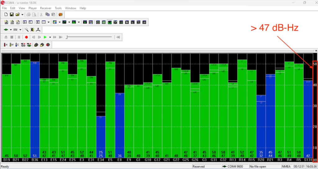
The “Survey-in” method typically requires an unobstructed open sky and strong GNSS reception. To ensure adequate signal strength, you can open the “Satellite Level” window in u-center. Look for 8 or more green vertical bars with a signal strength greater than 47dB, as shown in the diagram below. These indicate an acceptable signal quality.
Survey-in concludes when both requirements are successfully met. At this point, the receiver transitions into time mode and starts generating a base position message labeled “RTCM3 1005”. You should now observe that the “1005” message appears in black font.
“Fixed Mode” (Option 2)
If you are deploying the GNSS base station at a permanent location, we recommend this option. We also have a separate step-by-step instruction that guides you on how to obtain high-precision coordinates using a PPK (Post-Processing Kinematic) service.
How to obtain a highly accurate coordinate for your RTK base station?
In addition to using PPK, another option for obtaining high-precision coordinates is through RTK if it is available. In this case, you would need to manually enter the receiver’s position coordinates. You can select either the LLH position format, which includes latitude, longitude, and ellipsoid height (not the Mean Sea Level height).
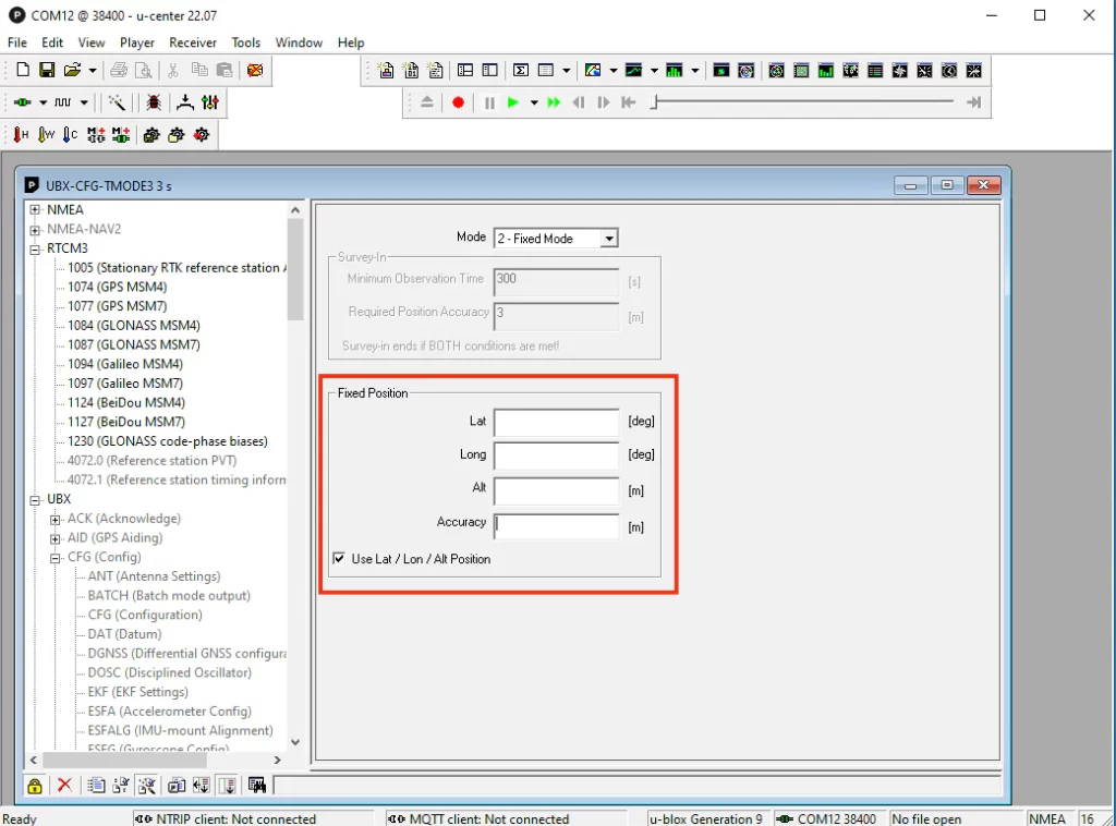
or ECEF position format (ECEF -X, ECEF-Y, ECEF-Z).
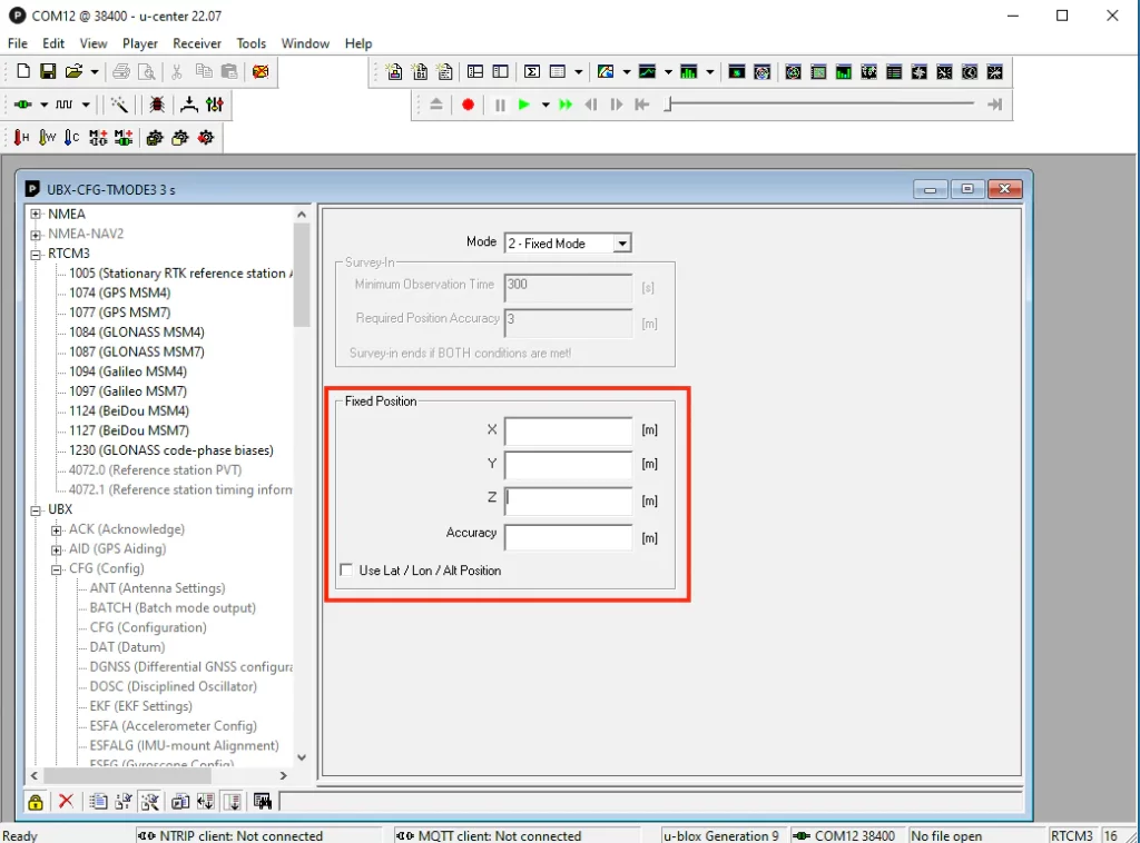
The accuracy of the base station position should be equal to or better than the desired accuracy for the rover’s absolute position. This is important because any error in the base station position will directly affect the accuracy of the rover’s position. In practical terms, we recommend setting the accuracy to 0.03 meters.
After making the necessary settings changes, please remember to click the “send” button twice to save the changes. If the base station is moved while in operation, you will need to configure the new position coordinates accordingly.
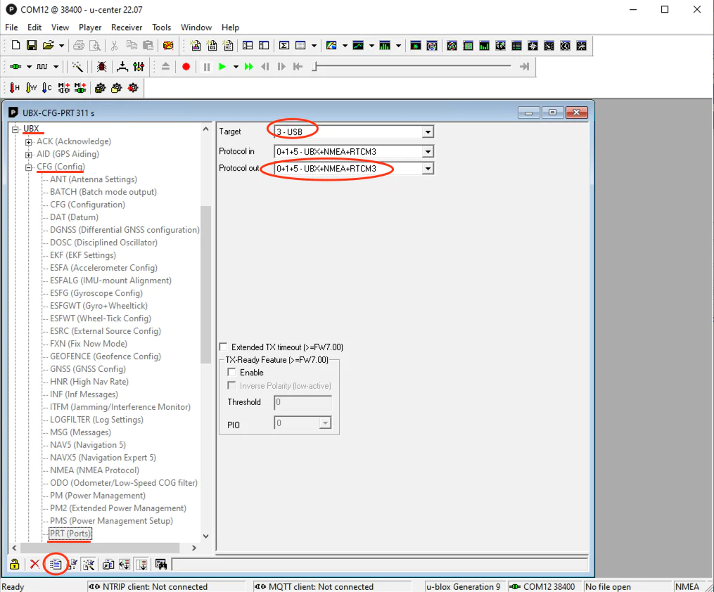
4. Configure USB port output RTCM message
In the u-center Message View Windows, navigate to UBX → CFG → PRT. Select the desired interface, such as “3 – USB.” For the “Protocol out” setting, choose either “5 – RTCM3” or “0+1+5 – UBX+NMEA+RTCM3” depending on your requirements. Remember to click the “Send” button twice to save the changes after adjusting the values.
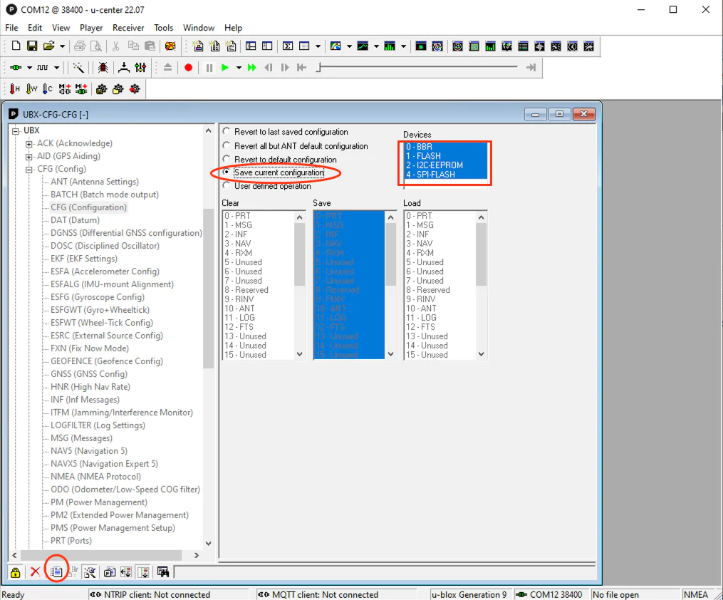
5. Save the configuration permanently
This step is crucial for saving all the previously made setting changes to the device. In the u-center Message View Windows, go to UBX → CFG → CFG. On the right panel, choose “Save current configuration” and ensure all “Devices” are highlighted. Finally, press the “Send” button twice to initiate the saving process.
Congratulations! Your GNSS receiver has been successfully configured as an RTK Base Station, capable of outputting RTCM correction data through the USB interface.
We have tested the below RTK GPS/GNSS receivers
work with this instruction.
They can be purchased from:
https://gpswebshop.com (US & WorldWide)
https://canadagps.ca (Canada)